

Fusion CAM
3-Axis CNC Machining of Sheet-Metal Parts
A complete CAM workflow in Autodesk Fusion — from imported model to finished toolpaths
Overview
This tutorial walks through the complete manufacturing (CAM) workflow for a flat, sheet-metal part in Autodesk Fusion, using 3-axis (often called 2.5-axis) milling. It assumes you are starting from a part that has been fully modeled — every edge filleted, the part lightened as appropriate, and the geometry finalized. In other words, the design is complete, and the only task that remains is to program the toolpaths that will fabricate it.
You will prepare the model, define the stock and machine origin, and then program each machining operation in the order a machinist would run them. Every operation is verified by simulation before you move on to the next one.
Preparing the Model
Importing the part
Begin by importing the part into Fusion. A model brought in from another CAD system usually arrives positioned wherever it sat when it was modeled, which may be some distance from the design origin.
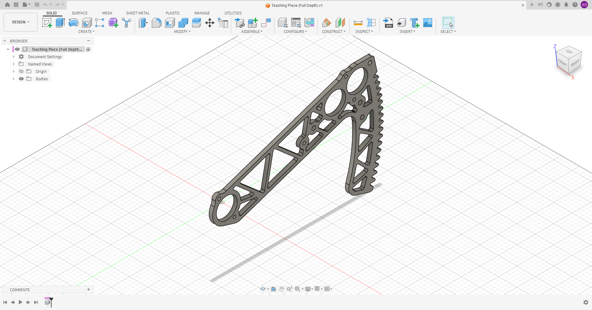
Before the part can be machined, it needs to lie flat and be located predictably relative to the origin.
Aligning the part to the origin
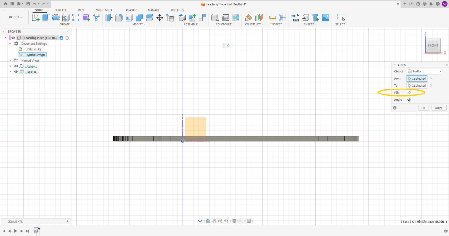
Use the Align command to reorient the part so that one flat face lies on the origin plane. Two things must be true before you start: the origin must be visible (confirm it is not hidden in the Browser), and the design must be set to the Hybrid design type — not Part and not Assembly. Hybrid is the classic Fusion design type; it lets you freely modify the imported body and add new geometry, such as the stock, in the same file.
Tip: Hover over the face you want to select, then hold Ctrl. This lets you pick from all of the alignment points along that face — including the center of a circular feature — instead of just the face itself.
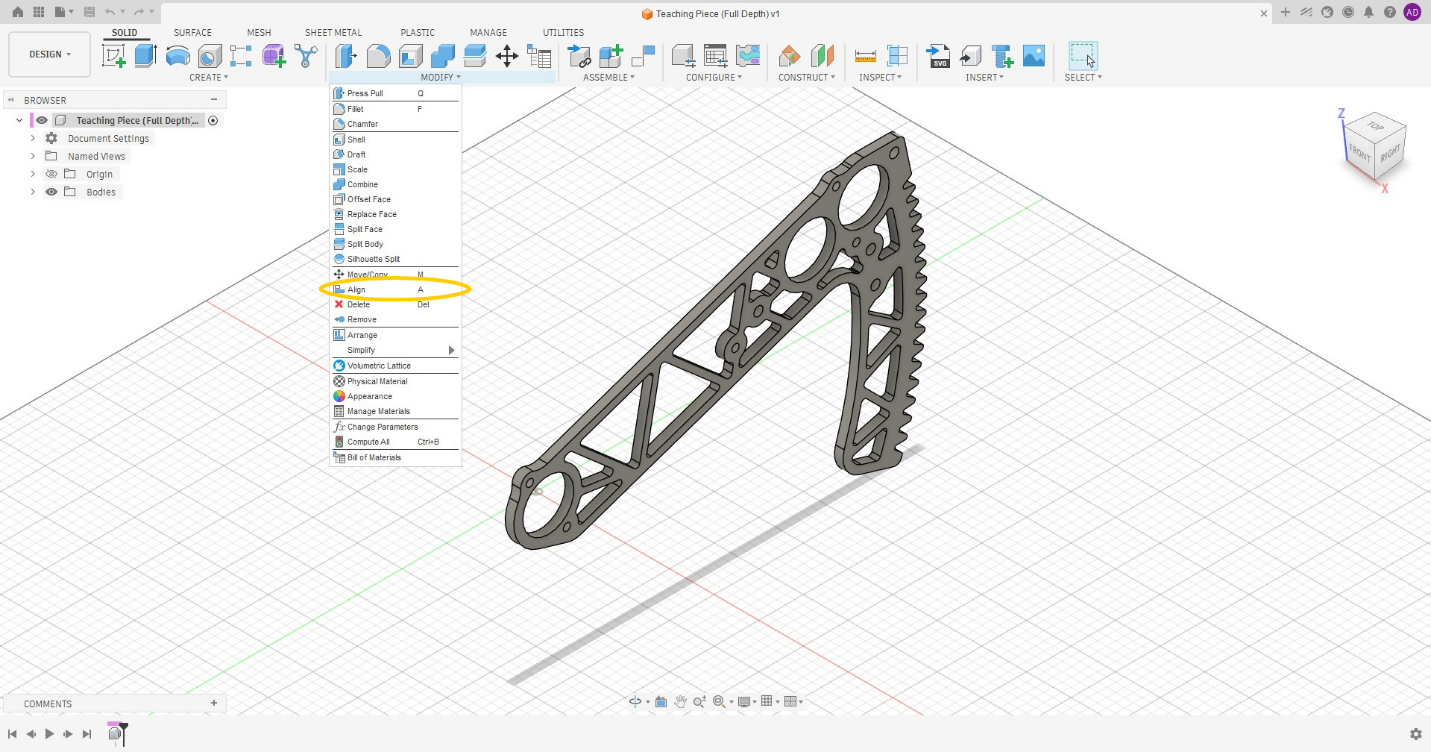
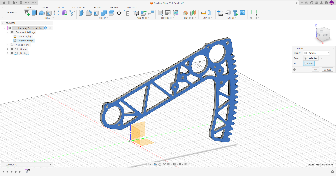
Align the selected face to the origin using the XY plane so that the part lies flat.
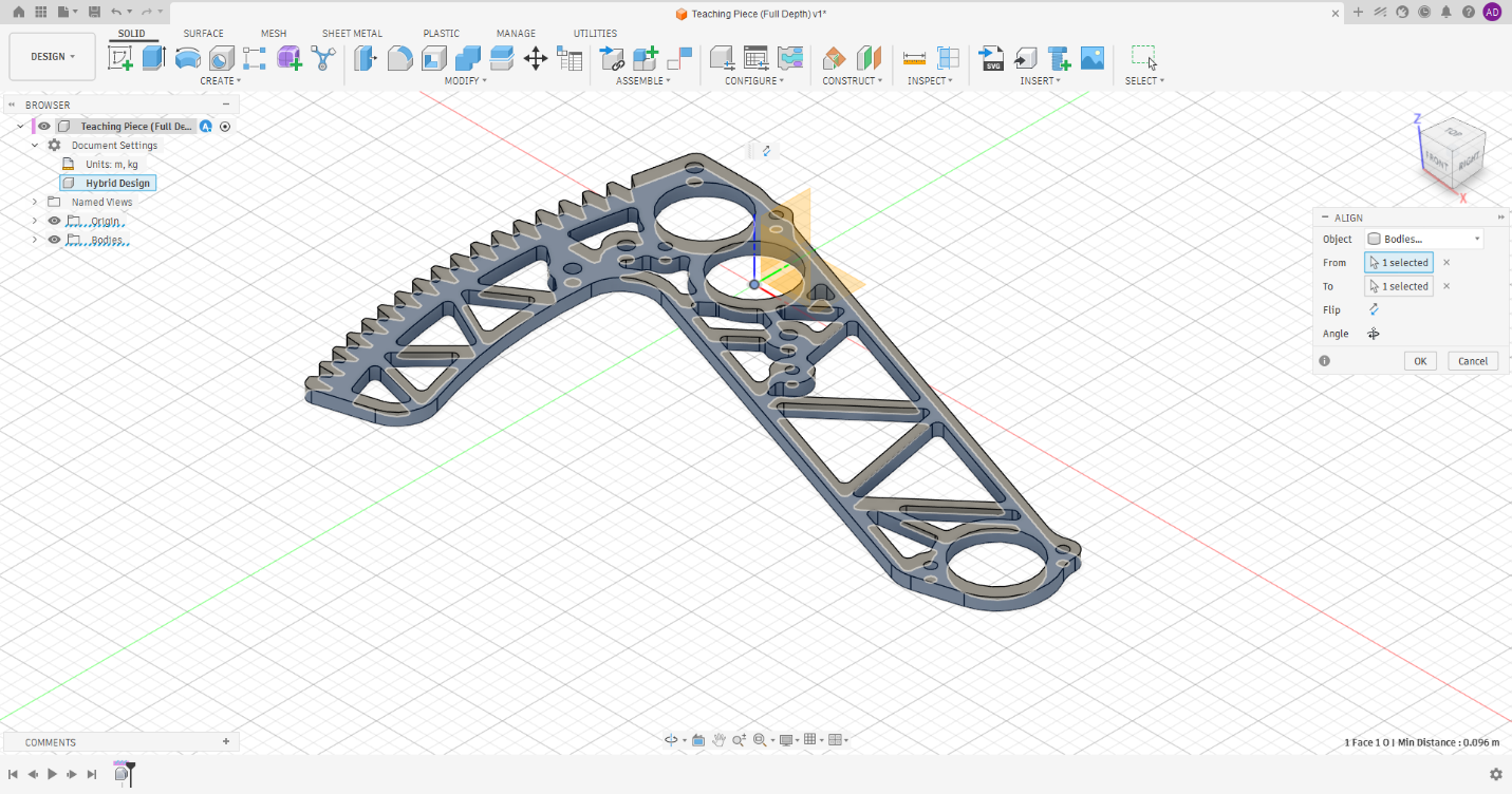
If the part ends up below the origin, use the Flip control in the Align dialog so the entire part sits above the origin, with one face flush against the XY plane.
Creating the stock body
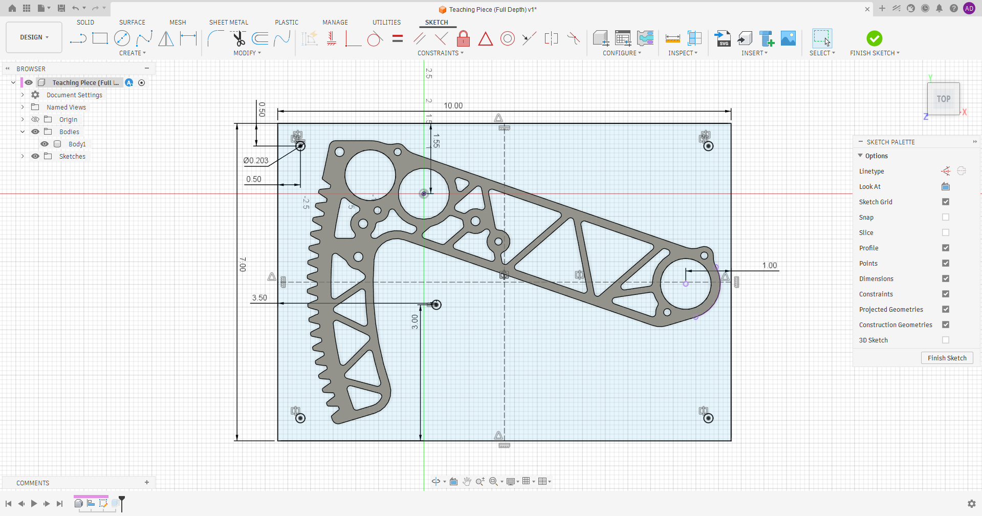
Next, model the stock. Create a simple rectangular sketch sized to the material you will cut from, and include the pre-drilled holes — [hole diameter to be confirmed with Robert] — that will be drilled manually on the drill press to secure the part to the spoilboard with wood screws. Use round, easy-to-measure dimensions so the stock is simple to cut and locate on the machine.
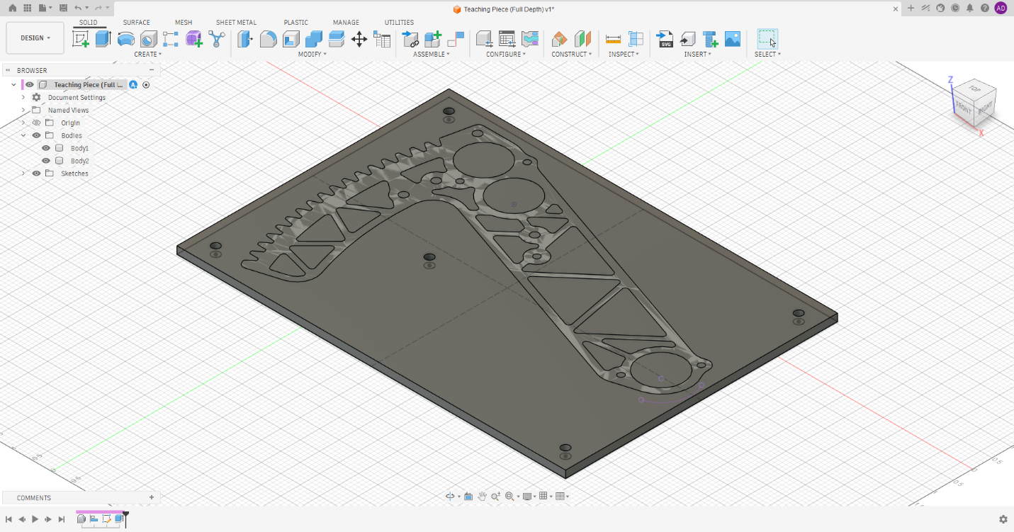
Extrude the sketch to the height of the part. For sheet-metal parts, the part height is typically the same as the stock thickness.
Setting Up the Manufacturing Environment
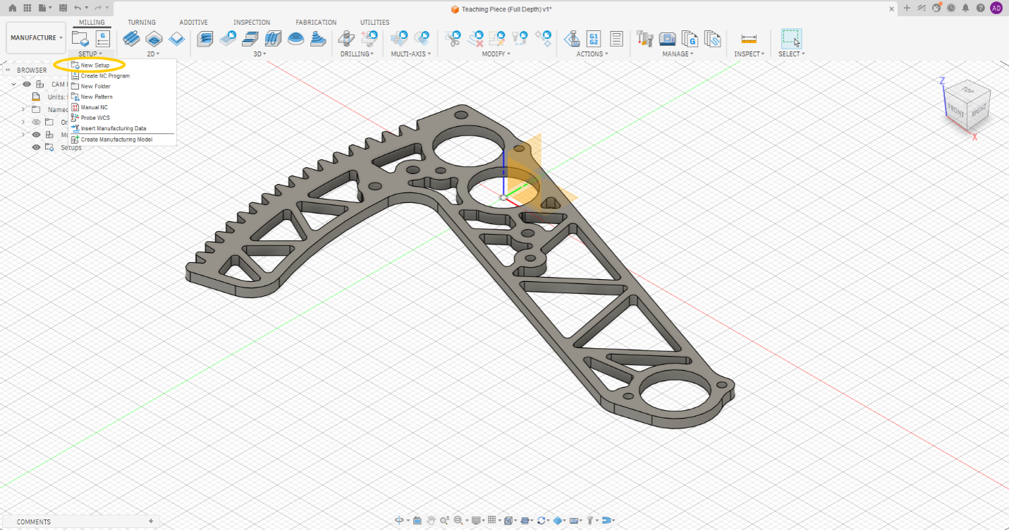
Switch to the Manufacturing workspace to begin programming toolpaths.
Creating a setup
Create a new setup. The setup defines the stock, the coordinate system, and which bodies are being machined; everything that follows lives inside it.
Defining the stock
Open the Stock tab. Set Mode to From Solid and select the stock body you just created. Using the solid body directly means the stock matches your extrusion exactly.
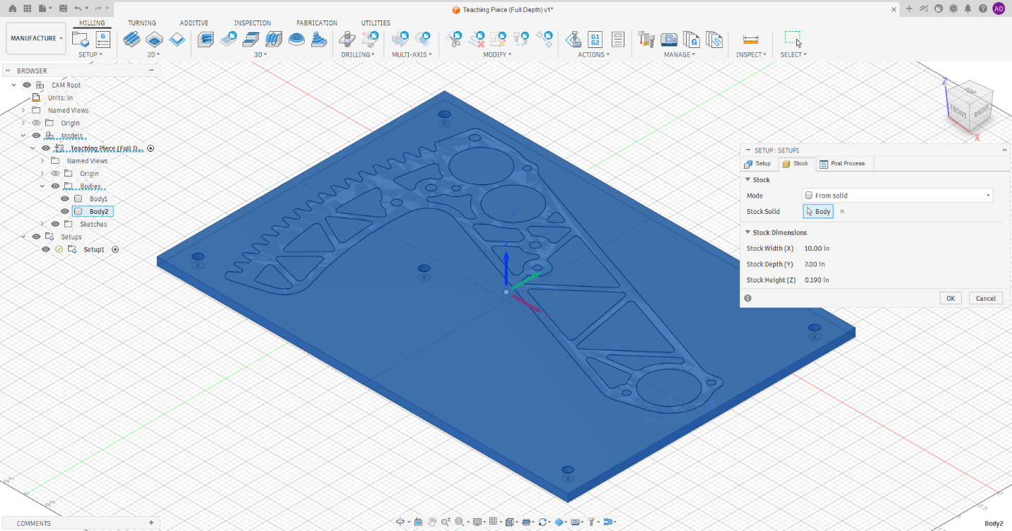
Once the stock is defined, hide the stock body — it is no longer needed in the view.
Setting the Work Coordinate System (WCS)
In the Setup tab, set the Work Coordinate System (WCS) origin. This is the point the machinist will set as zero on the machine, so it must be easy to locate on the physical stock. Set Origin to a stock box point and pick a top corner of the stock. Always choose a point on the top surface of the stock, because the operator touches off from the top face.
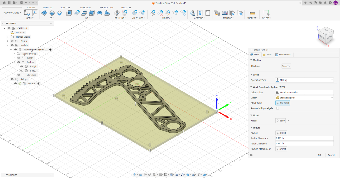
Machining Operations
Operation 1 — Bore the fastener holes
The first operation is always a Bore, used to cut the holes the fasteners pass through. These same holes hold the stock down to the spoilboard while the rest of the part is machined, which is why they are cut first.
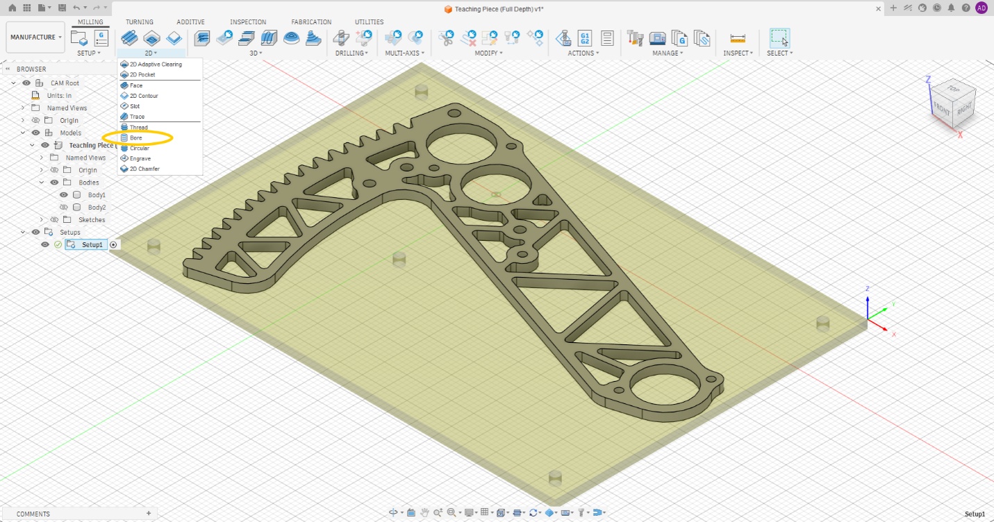
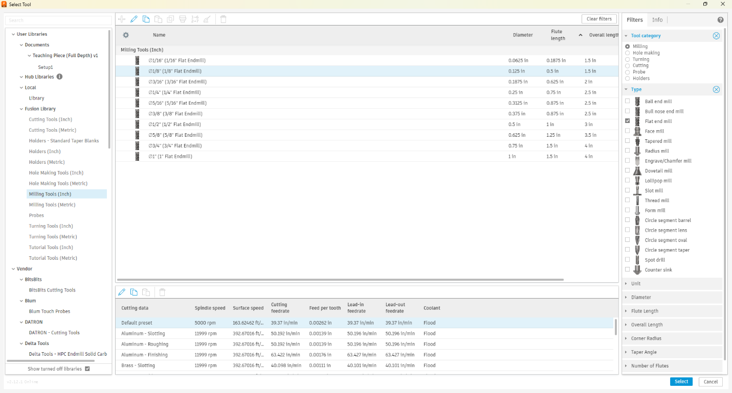
First, select a tool. For the vast majority of this work you will use the 1/8 in end mill shown below; use the tool-library filters to find it quickly. Then, on the Tool tab, make sure Coolant is disabled.
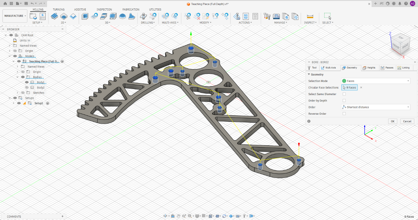
Open the Geometry tab and select the interior of every hole to be bored. Be careful not to accidentally select the small pockets, and do not select the bearing holes even though they are circular — those are handled by later operations.
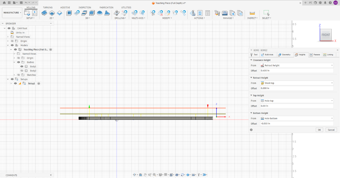
On the Heights tab, set the Bottom Height to the hole bottom with an Offset of -0.010 in. Cutting just past the bottom guarantees no material is left behind at the base of the hole.
On the Passes tab, match the settings shown.
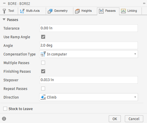
These passes bore out the full hole while leaving a clean finish — suitable for tapping or for a clearance fit.
On the Linking tab, turn on Lead to Center. This sends the end mill to the center of the hole before it begins boring, which prevents it from colliding with leftover stock ahead of the finishing pass.
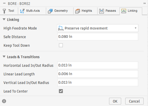
The first operation is complete. Before moving on, simulate it. Always simulate after creating or editing an operation to confirm the toolpath behaves as intended.
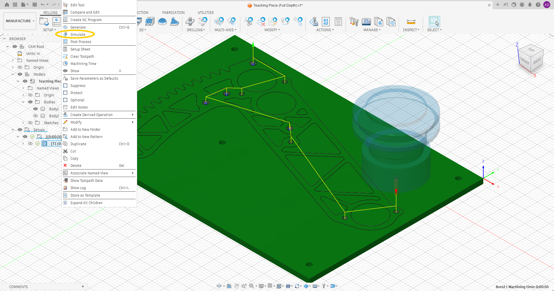
Operation 2 — Rough the full-depth lightening with 2D Contour
The next operation removes most of the lightening material using a 2D Contour. Important: a contour only works on lightening features that are full depth — that is, they pass all the way through the part. For partial-depth features, where material is left at the bottom, see page XX (“Machining Partial-Depth Pockets”).
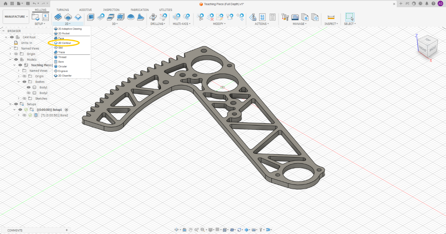
As before, make sure Coolant is disabled and the same 1/8 in end mill is selected, then open the Geometry tab.
A 2D Contour works like a cookie cutter: the tool ramps down around the outline of your selection — here, the lightening pattern — isolating the material in the middle and clearing large chunks of stock quickly. Do not use a contour when the pocket is small, because it will not clear reliably; small pockets are handled separately below. Click the bottom edges of all of the lightening holes and the bearing holes to tell the contour where to cut.
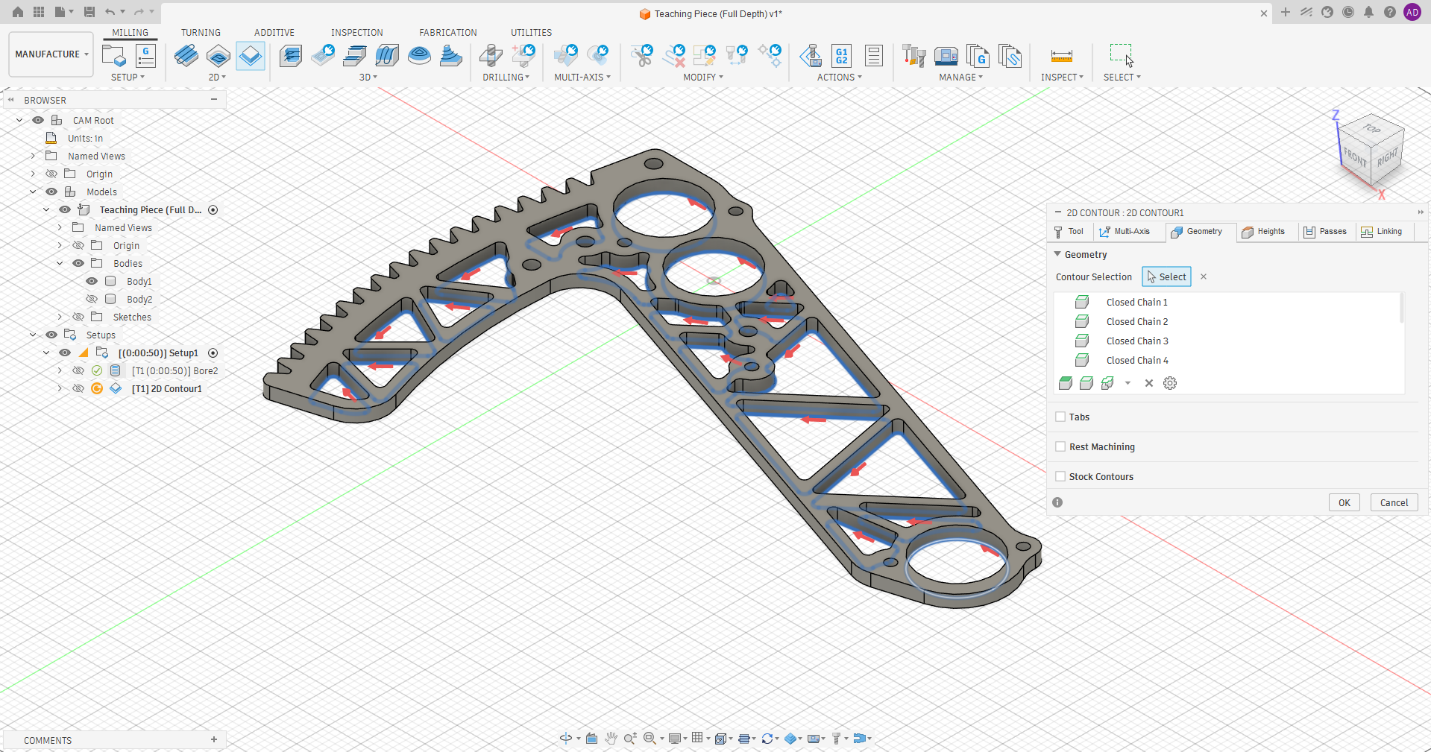
Set the Heights the same way as before so that no material is left at the bottom.
On the Passes tab, collapse Passes, then enable and expand Roughing Passes and match these settings.
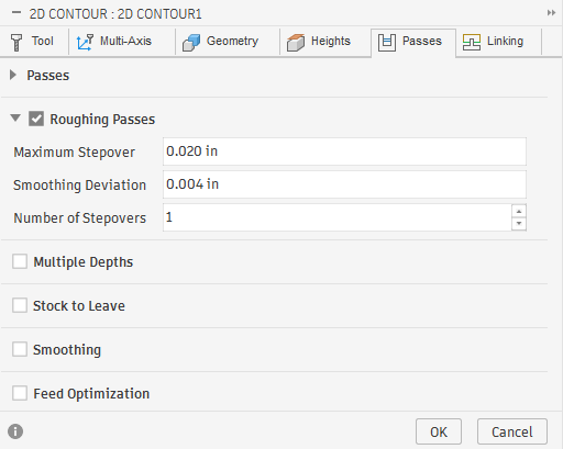
With these settings, the toolpath leaves a small amount of material on the rib walls as it steps down, then clears that material after each stepdown. You will correct this behavior in the Multiple Depths settings. Match the following.
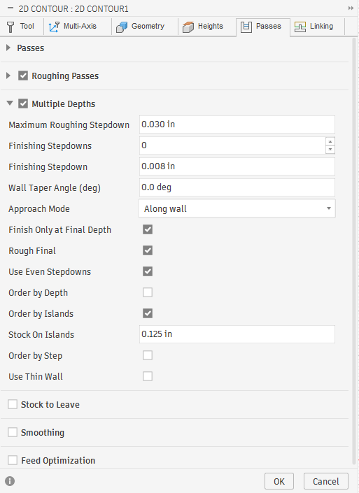
Reducing the Maximum Roughing Stepdown conserves the end mill by removing less material per pass in Z. Finishing only at final depth fixes the roughing stepover issue: instead of cleaning the walls after every stepdown, the tool removes that material once at the end, leaving a better finish in less time. Using Even Stepdown further conserves the tool by distributing the stepdowns evenly across the total depth that must be removed.
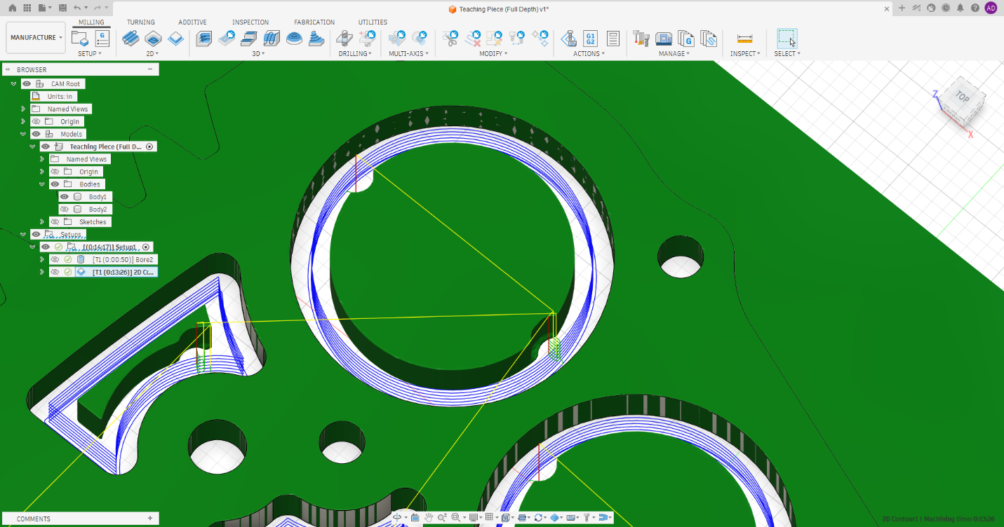
A bearing-hole toolpath should look like the image below — each stepdown pass, followed by the final finishing pass that extends slightly past the bottom.
When not to contour: small “cookies”
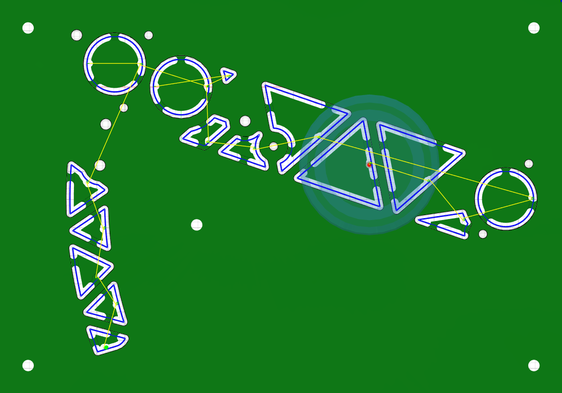
Notice that some of the pockets leave very small “cookies” — the chunk of material isolated in the middle of a contour. The pocket circled in teal is a lucky case: the contour produced no error and leaves essentially no cookie at all.
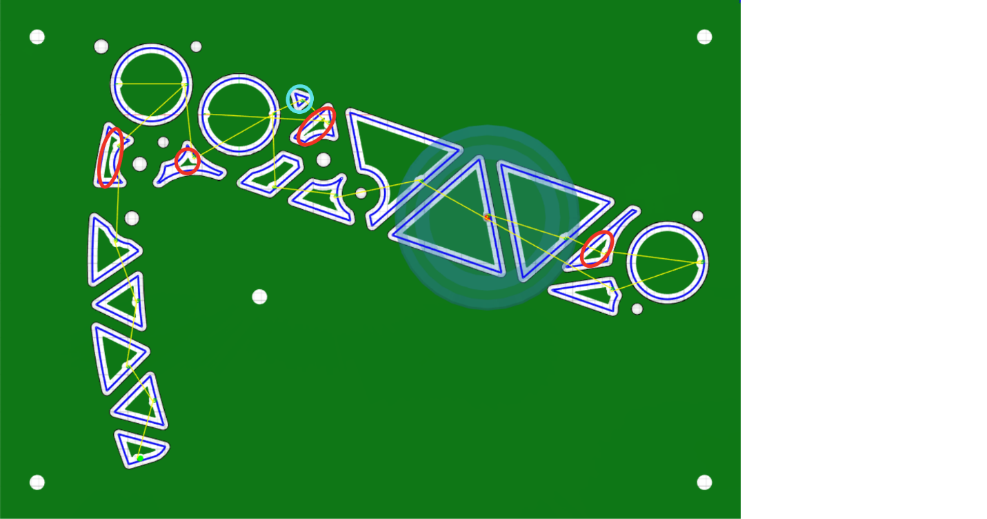
The reason to avoid contouring pockets that leave a small cookie is safety. A small cookie can shift or break loose, catch on the end mill, and cause damage, whereas larger cookies can be held securely (see Tabs, below). For those small pockets it is worth spending a little extra time to clear the material completely, which is covered in Operation 3. For now, deselect the small pockets: on the Geometry tab, hold Shift and click the corresponding edges to remove them from the selection.
Holding material in place with tabs
So how do the larger cookies stay in place? The answer is tabs. Enable the Tabs option and match the settings shown. Tabs are small, thin pieces of material left behind to hold a cookie in place during machining; they are broken off by hand afterward and, once filed, deburred, and sanded, leave no trace.
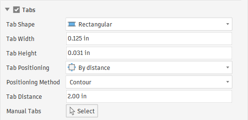
Increasing the Tab Distance keeps Fusion from adding more automatic tabs than necessary and lets you place your own tabs manually. Use a minimum of two tabs holding different sides of the cookie. For very large cookies — such as those left by bearing holes — three tabs are sufficient.
Click along the selected edges wherever you want a tab. The positions do not need to be exact; use your judgment. The example below shows one workable arrangement.
Operation 3 — Clear small pockets with 2D Pocket
Now clear the small pockets that were deselected earlier. This costs only a little extra time and removes the material completely. Use a 2D Pocket operation.
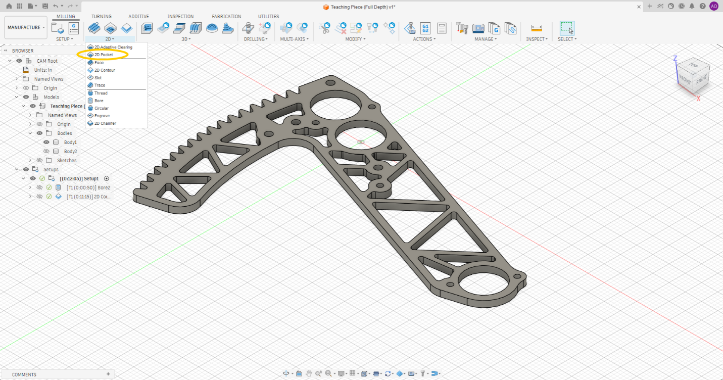
Again, make sure Coolant is disabled and the same 1/8 in end mill is selected. On the Geometry tab, click the bottom edges of the remaining lightening holes, then set the Heights the same way as before so no material is left at the bottom.
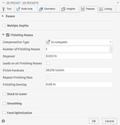
On the Passes tab, collapse Passes and clear Stock to Leave. Then enable and expand Finishing Passes and match these settings — the reasoning from earlier applies.
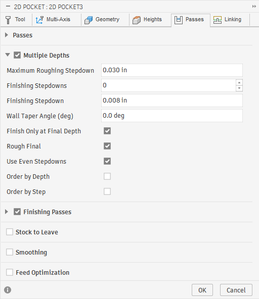
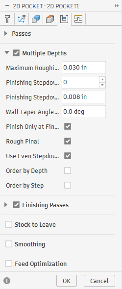
Enable and expand Multiple Depths and match these settings; again, the earlier reasoning applies.
Operation 4 — Cut the part from the stock
With the interior lightening cleared, the last step is to cut the part itself out of the stock. Use a 2D Contour, select the bottom outer edge of the part, and apply the same settings as before — but without tabs — then review the result.
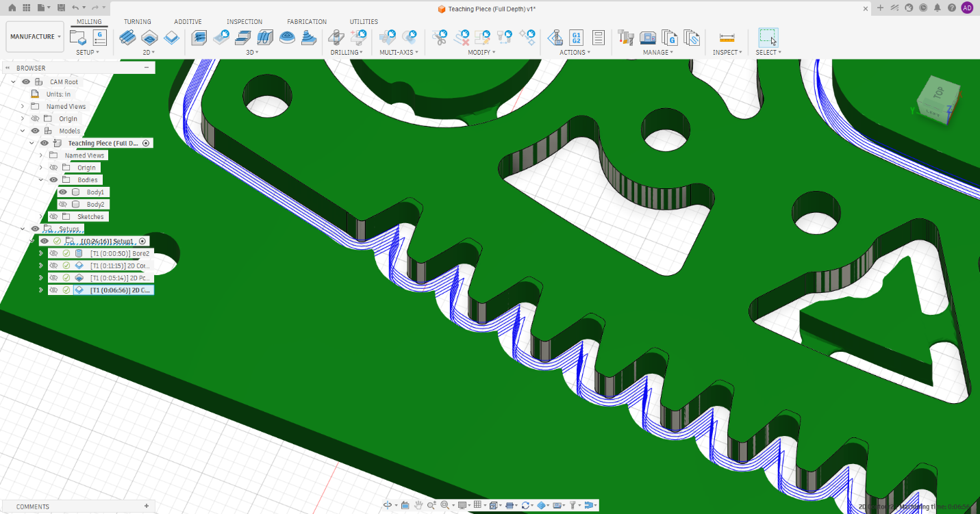
You will see that some material remains: the end mill is not small enough to reach into certain areas without removing too much material.
To clean this up, run a second contour with a smaller end mill and slightly different settings. The result should look like the image below. Consult an experienced team member when setting this up.
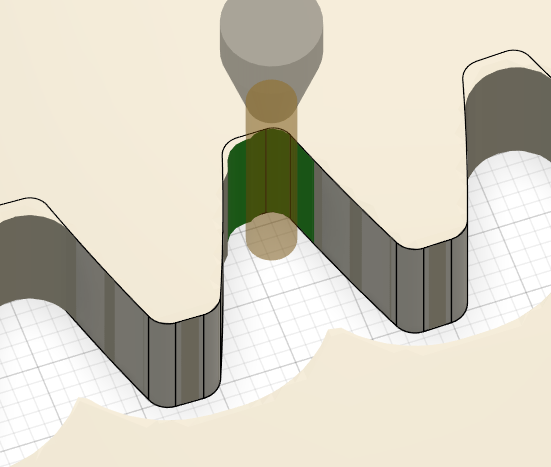
Machining Partial-Depth Pockets
What about pockets that are not full depth — features that do not pass all the way through the part? These cannot be cleared with a 2D Contour: because the pocket floor remains, a contour would only trace the profile and leave the interior material standing. Instead, use a 2D Pocket to remove material down to the required depth while leaving the floor intact.
The model below has already been set up, with the first operation (Bore) completed. To create the partial-depth pockets, add a 2D Pocket operation. As always, make sure Coolant is disabled and the same 1/8 in end mill is selected, then open the Geometry tab and select the face of each pocket you want to clear.
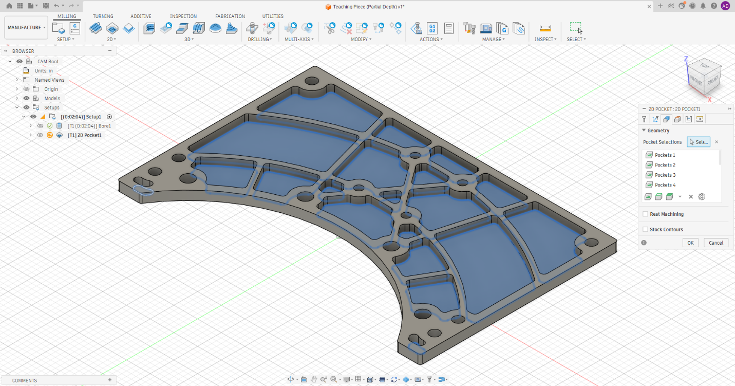
There is no need to change anything on the Heights tab — you do not want to cut any deeper than necessary, and you want to leave material at the bottom of the pocket.
On the Passes tab, collapse Passes and clear Stock to Leave. Then enable and expand Finishing Passes and match these settings; the earlier reasoning applies.
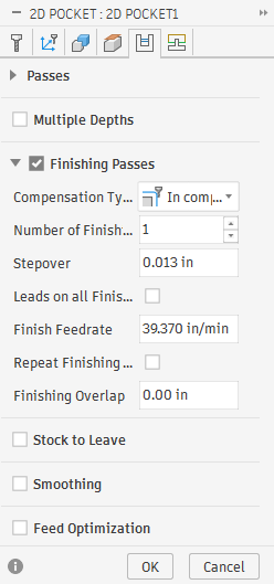
Enable and expand Multiple Depths and match these settings; again, the earlier reasoning applies.
Finishing Up
Finally, use a 2D Contour to cut the finished part out of the stock, exactly as in Operation 4.
That is it — you can now program a sheet-metal part for CNC fabrication from start to finish on your own.